Switchgear
Switchgear Failure Identification
The maintenance of circuit breakers deserves special consideration because of their importance for routine switching and for protection of other equipment. Electric transmission system breakups and equipment destruction can occur if a circuit breaker fails to operate because of a lack of preventive maintenance. The need for maintenance of circuit breakers is often not obvious as circuit breakers may remain idle, either open or closed, for long periods of time. Breakers that remain idle for 6 months or more should be made to open and close several times in succession to verify proper operation and remove any accumulation of dust or foreign material on moving parts and contacts.

Recommended Electrical Test
Online Test
Visual Inspection
– Breaker Condition
– Main Power Connection
– Wiring Control Cable, Terminal Cable, Cable Marker
– Grounding Cable, Wiring and Connection
Power Monitoring
– Volt Indicator
– Ampere Indicator
– Frequency Indicator
– Power Indicator
– Lamp Indicator
Infrared Thermography
Perform thermography survey on the terminal box and corresponding electrical cable systems with the unit online. This will detect any hot spots caused by abnormally high electrical resistance, which requires attention.
– Cable
– Terminal Cable Connection
– Component & Accesories
– Busbar
– Terminal Busbar Connection
Offline Test
Insulation Resistance & Polarization Index
Contact Resistance
Motor Current
Close & Open Timing
Dynamic Contact Resistance
Minimum Pickup
Mechanical Test
Secondary Current Injection Test
Current Transformer Test
Voltage Transformer Test
Insulation Resistance & Polarization Index Test
Purpose
Insulation Resistance
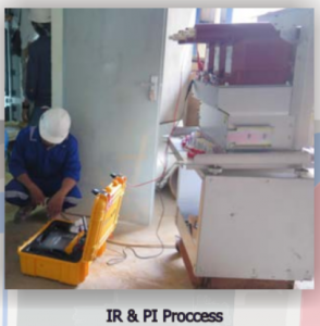
This measurement aims to determine the condition of the insulation both phase to phase and phase to ground. Basic principle of these test is measure by injecting DC Voltage, then measure the insulation resistance from 1st minute to 10th minutes.
Polarization Index
This measurement aims to determine if equipment is suitable for operation or even for an overvoltage test. Total current that is developed when applying a steady state dc voltage is composed of three components:
– Charging Current
– Absorption Current
– Leakage Current
Method
Fluke 1555 may be used to make tests between phases of opposite polarity and from current-carrying parts of the circuit breaker to ground. A test should also be made between the line and load terminals with the breaker in the open position. Load and line conductors should be disconnected from the breaker under insulation resistance tests to prevent test mesurements from also showing resistance of the attached circuit. Resistance values below 1 megohm are considered unsafe and the breaker should be inspected for possible contamination on its surfaces.

Minimum Pick Up Test
Purpose
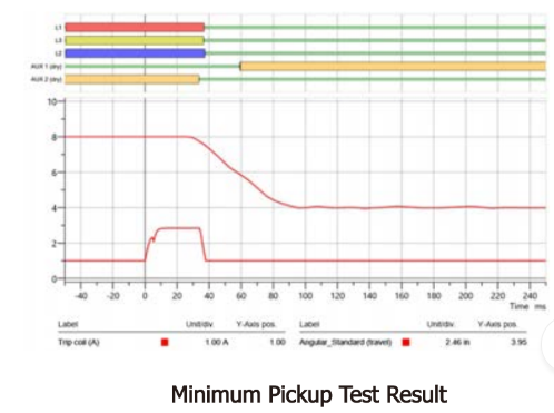
This test determine the minimum voltage necessary to trip and close a circuit breaker. It makes sure that a circuit breaker can also be reliably operated in the event of a low DC supply.
Method
The test begins at a low voltage, sending a control pulse to the breaker. The voltage is increased by small increments until the breaker operates; this voltage is recorded and is expected to remain unchanged through future dates.

Open & Close Timing Test
Purpose
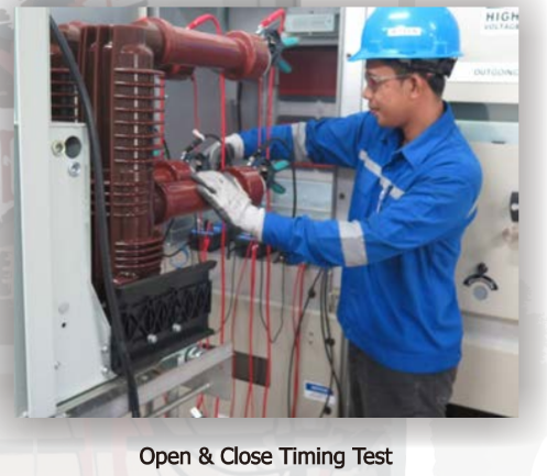
The main contact timing is assessed by measuring the time from test initiation to the change of main contact state. The test can detect incorrect mechanical adjustments or wear phenomena of a circuit breaker.
Method
Open Timing Test
– Make sure the circuit breaker is close
– Measure the open time when the circuit breaker is open
– Check the open time between phase R, S and
Close Timing Test
– Make sure the circuit breaker is open
– Measure the close time when the circuit breaker is open
– Check the close time between phase R, S and T

Contact Resistance
Purpose
Increased contact resistance can be caused by pitted contact surfaces, foreign material embedded on contact surfaces, or weakened contact spring pressure. Contact resistance should be measured to knowing the excessive current diverted through the arcing contacts, with consequent overheating and burning.
Method
Contact resistance can be measured by measuring the travel of the lift rod from the start of contact opening to the point where contacts separate as indicated by an micro ohm meter.

Dynamic Contact Resistance
Purpose
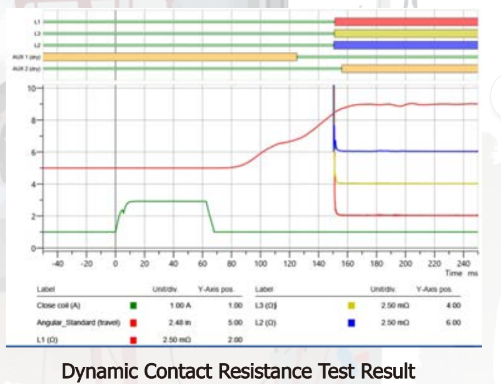
Dynamic contact resistance measurement (DCRM) is advance technique for assessing the condition of power circuit-breaker (CB) main contacts and arcing contacts.
Method
The measurement is performed by injecting DC current through the breaker and simultaneously monitoring the voltage drop as well as current flow during the operation of the breaker. From these two parameters a resistance value can be calculated.
