Generator Overhaul & Rewinding
Our Services & Works
Design & Machine Engineering
- Design/redesign of all electrical machines, cores, windings, retaining rings, supports, blocking and insulation.
- Protection system design.
- Replace shaft and another mechanical
- Excitation and automatic voltage regulator (AVR) system design and supply.
- Providing solution to inherent design issues for rotating machines.
Repair & Refurbishmnet
- Repair, rewinding and retrofit rotating electrical equipment, from 380V up to 12,8KV.\
- Repair of static and rotating.
- Workshop engineering and on-site diagnosis.
Installation &
Commissioning
- New machines.
- Repaired/ refurbished machines.
- On-site equipment commissioning
Site Services
– Electrical maintenance (with or without unit shutdown).
– Non-destructive testing (electrical and mechanical).
– Condition-based maintenance
– Value system maintenance and auto

Workshop Base Repair &
Overhaul
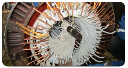
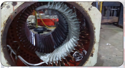
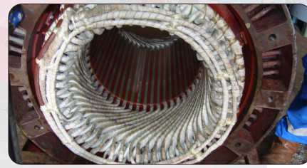
– Overhaul or rewinding AC motor & generator, stator & rotor, LV/MV/ HV winding.
– Overhaul or rewinding DC motor & generator, stator & armature winding
– Repair or replacement commutator, slip rings, brush holder, carbon brush and etc.
On-site Repair & Overhaul
– Overhaul AC/DC motor * AC/DC generator.
– On-site vibration analysis & in-site balancing.
– On-site laser alignment
– On-site winding analysis and life assessment for motor & generator
– Condition monitoring (off-line & on-line)
– Preparing and manufacture special equipment for extracting rotor generator on-site repair or overhaul and etc.

New Equipment & Spare
Part Supply
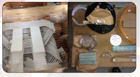
– Design, manufacture and reverse- engineering to DEM specifications.
– Supply new electric motor AC/DC. New Equipment & Spare Part Supply
– Sourching of replacement machines and associated parts.
– Supply of motor and generator auxiliaries part (fan blade, terminal & etc.).
Flow Chart Job Process at PT. Technodrives Workshop

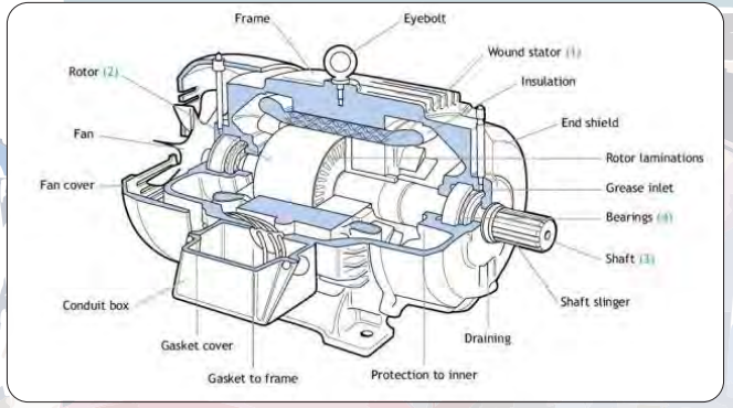
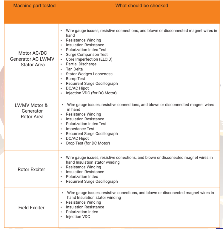
Rotating Machine Parts and Recomended Electrical Test
Detecting Faults to Prevent Failure
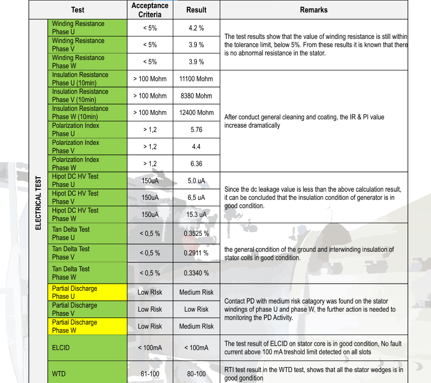
Electrical static tests are part of a series of activities performed during overhaul. Electrical static test aims to determine the condition of the generator that can not be captured by visual check. The series of tests is refers to the international standards and also the standard of manufacturer, in this case the Alstom generator.
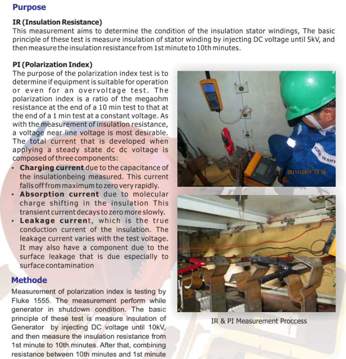
Insulation Resistance & Polarization Index Test
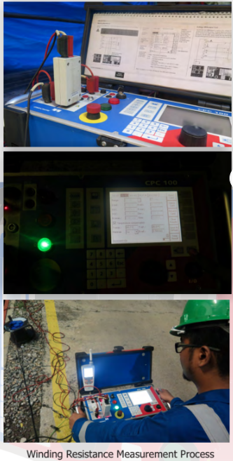
Winding Resistance Measurement
Purpose
The winding resistance test is used to find open windings, shorts to ground, wrong turn count, wrong wire gauge, resistive connections, round wires in hand that are not connected in a coil, some connection mistakes, the resistance balance between phases, and in some cases shorted turns.
Winding resistance is an important measurement WHY USE FLUKE 1555 ? CPC 100 because other tests and measurements will not find some of the problems a resistance measurement will find. Some of these are the wire gauge issues, resistive connections, and blown or disconnected magnet wires in hand.
Method
The basic principle of these test is DC current injection on the generator windings and then measure the DC voltage at the ends of the windings in the current injection. The value of winding resistance expressed in Ω (ohm) and is calculated by comparing the measured voltage to the supplied/injected current.
Tan Delta Measurement
Purpose
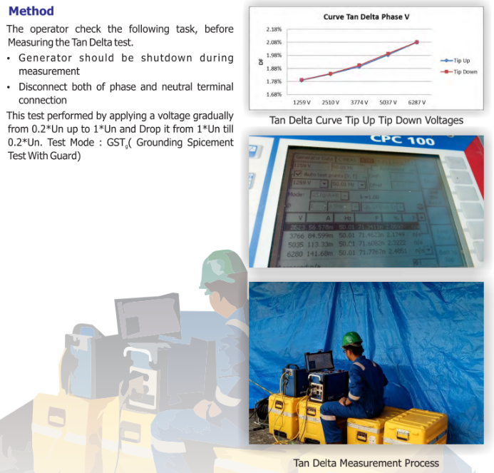
The power factors recorded for routine overall tests on older apparatus provide information regarding the general condition of the ground and interwinding insulation of stator coils. They also provide a valuable index of dryness, and are helpful in detecting undesirable operating conditions and failure hazards resulting from moisture, carbonization of insulation, defective bushings, contamination of oil by dissolved materials or conducting particles, improperly grounded or ungrounded cores, etc. Figure 6 Shows the equivalent circuit & vector insulation of stator coils.
Partial Discharge Measurement
Surge Comparison Measurement
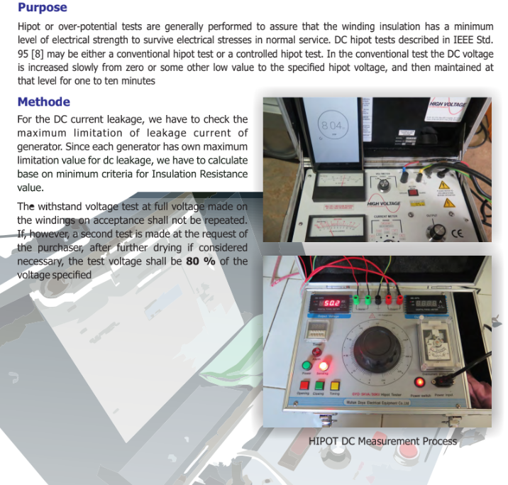
High Voltage (Hipot) DC Measurement
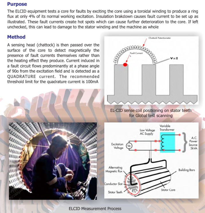
ELCID Measurement
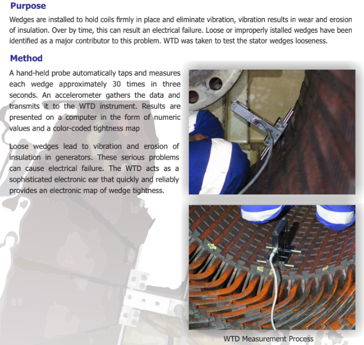
Wedge Tightness Detector (WTD) Measurement
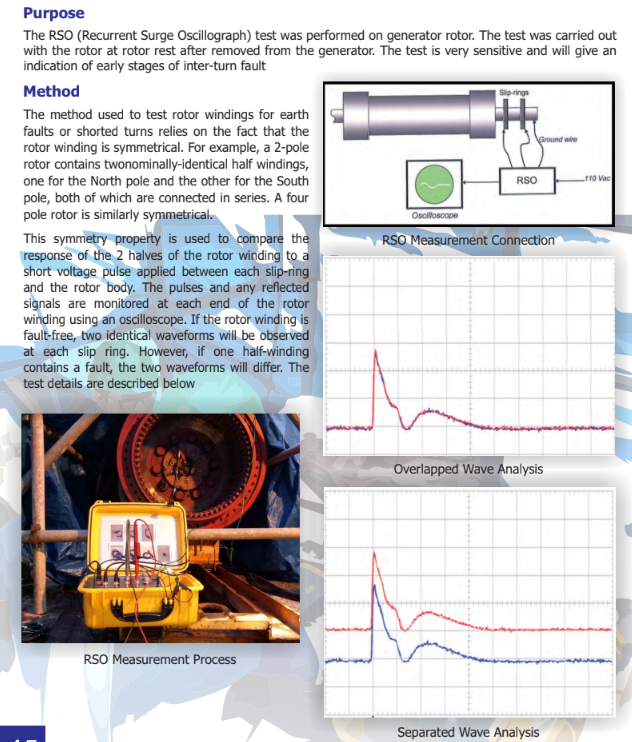
Repititive Surge Oscillograph Measurement
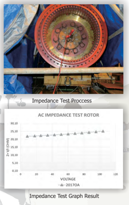
AC Impedance Measurement
Purpose
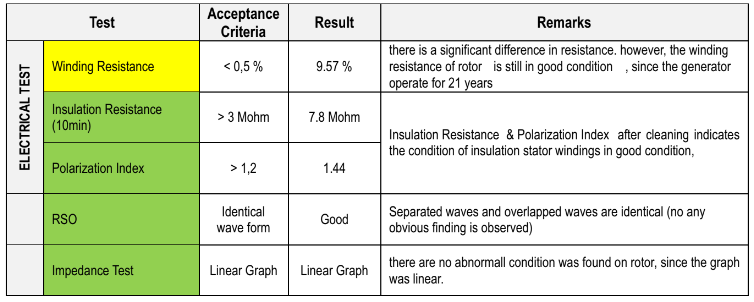
The impedance of the winding under test can be measured at standstill on all multiturn salient or cylindrical field coils or at speed on those with collectors. An impedance curve can be established by varying a power frequency voltage, measuring the current, and calculating the impedance. It is important that comparisons be made on similar conditions of rotor environment such as assembled or unassembled. Similar conditions of assembly should be used for comparison. The presence of magnetic material could affect the results, therefore the field should be elevated from steel reinforced floors or bed plates.
The test results will change depending on the presence of factors changing the characteristics of the impedance. Shorted turns will be detected by a step change in impedance when shorted turns appear either by voltage or speed changes. If shorted turns are present at all speeds and/or voltages, a comparison to the “as new” impedance or prior satisfactory test will show the change necessary to conclude that shorted turns are present. Field coils are reasonably uniform in structure so that the impedance characteristics at a fixed current will produce the comparable voltage drops across all coils unless shorted turns are present. Slight differences may occur with open and crossed wound field coils, however the alternate pattern of these coils can be compared.
Method
The maximum test voltage is limited by either the voltage source or the current capacity of the variable auto transformer. This voltage should be determined by raising the voltage to the limiting factor. The maximum test voltage should be divided into 10 equal increments. Starting at the minimum voltage step, the voltage should be raised through each step, measuring and recording the voltage and the current until the test is completed at the maximum
voltage. The impedance should be calculated for each step and the results plotted as a function of the voltage. As the voltage is raised, the presence of shorted turns should appear in the results as a lower impedance. The amount of the step change in impedance can be used to calculate the number of shorted turns present.
Electrical Test Overview
STATOR TEST
ROTOR TEST
BRUSHLESS EXCITER TEST

BEARING TEST

RTD TEST

DIODE WHEEL AND ARMATURE TEST

POWER QUALITY TEST

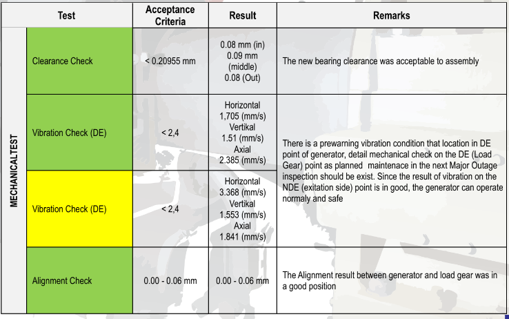
Mechanical Test Overview
STATOR TEST

ROTOR TEST

ROTOR TEST
